2. Overview of AC charging device
AC charging facilities are devices that provide AC power for electric vehicles, generally consisting of relays/contactors, control pilot circuits, leakage protection circuits, overvoltage protection circuits, metering modules, lightning protection modules, communication modules, human-machine interaction interfaces, etc. Their rated capacities include 2.2kW (220VAC, 10A), 3.3kW (220VAC, 16A), 6.6kW (220VAC, 32A), and 22.4kW (380VAC, 63A). The charging connection device is the physical transmission medium between the charging device and the electric vehicle.
The physical dimensions, mechanical structure, electrical characteristics, etc. of the charging connection device used for charging shall comply with the relevant requirements of GB/T 20234.1-2015 "Connection Devices for Conductive Charging of Electric Vehicles - Part 1: General Requirements" and GB/T 201234.2-2015 "Connection Devices for Conductive Charging of Electric Vehicles - Part 2: AC Charging Interface" to ensure the physical adaptability of the charging connection. There are three types of connection methods for connecting devices: A, B, and C3. According to the latest implemented standard GB/T18487.1-2015 "Conductive Charging Systems for Electric Vehicles - Part 1: General Requirements", only charging modes 2 and 3 are applicable to AC charging. Table 1 shows the usage conditions for the two charging modes. Charging that does not meet the conditions will result in the inability of electric vehicles to charge, and in severe cases, may cause safety accidents.
3. OBC principle
The charger is composed of rectifier circuit, adjustment control and protection circuit, power factor correction network, auxiliary circuit, charger control and management unit (CPU), human-machine interface unit, remote communication unit, electric energy metering unit, and other parts.
Input interface, 7 pin ports, three types of connections, including high-voltage power connection and high-voltage neutral line; Vehicle chassis ground; Confirm the charging connection and control of low voltage signals. The standard input interface adopts a power frequency single-phase input voltage of 220V. But if power is needed, two backup pin ports (pin ports NC1 and NC2) can also be enabled to achieve 380V input.
The control unit samples the output current and voltage, and after processing, transfers the real-time values to the PID (a closed-loop automatic control technology, abbreviated as proportional, integral, and differential controller) control circuit. The controller compares the difference between the measured value and the expected value, and then transfers the adjustment requirements to the PWM circuit (PWM pulse width modulation technology). The pulse width change is used to control the opening and closing time of the power device in the high-voltage circuit, The final output current and voltage should be as close as possible to the values required by the main control system.
Low voltage auxiliary unit is a standard low-voltage power supply with an output voltage of 12V or 24V, used to supply power to electrical appliances on electric vehicles during charging, such as battery management systems, thermal management systems, automotive instruments, etc.
The power unit generally includes three parts: input rectifier, inverter circuit, and output rectifier, which convert the input power frequency AC power into DC power suitable for the appropriate voltage that the power battery system can accept.
Output port, including two pin ports for the positive and negative poles of the low-voltage auxiliary power supply, two pin ports for the positive and negative poles of the high-voltage charging circuit, chassis ground, communication lines CANH and CANL (which can also have CAN shielding), and charging request signal line. Among them, a high-voltage pin port is connected to the battery pack; The charging request signal line is used to send a charging request signal to the vehicle controller through the "charging request signal" line after confirming the charging connection between the input port of the charger and the external power supply. At the same time, or after a short delay, the low-voltage auxiliary power supply is used to power the entire vehicle.
OBC includes microcontroller 1 and microcontroller 2, as well as DSP. Some manufacturers only have one microcontroller, and the CC/CP part is directly implemented using DSP. ARM control of communication piles K1, K2, S1. Single chip microcomputer 1 controls K3. Single chip microcomputer 2 controls S2. DSP controls K4. BMS controls K5, K6 in the PDU and K7 in the power battery pack. K5 represents the pre charging contactor, K6 represents the slow charging contactor, and K7 represents the total negative contactor of the power battery.
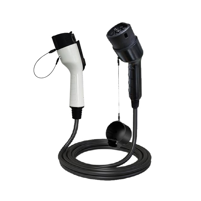
4. AC charging connection device
The AC charging mode can be used in modes 2 and 3. Mode 2 is to use a "cable controller" for charging, with one end being an AC plug, one end being a charging gun, and the small black box in the middle being the "cable controller" (now gradually referred to as Mode 2 charging box). Mode 3 uses an AC pile for charging. The most common connection methods are Connection Method B and Connection Method C. Connection method B refers to the AC gun wire that can be taken out of the AC pile, while method C is fixed on the AC pile. The common method on the market is method C. In terms of circuit principle, the connection mode B and connection mode C of mode 2 and mode 3 are the same.
The circuit responsible for shaking hands inside the communication pile is called the "power supply control guidance device", and the one on the vehicle end is called the "vehicle control device". The AC pile actually only has one circuit board, and the "power supply control guidance device" is only a part of the circuit units on the AC pile circuit board. The 'vehicle control device' was initially implemented by car companies through vehicle controller VCUs or battery management systems (BMS), but now it is gradually being transferred from car companies to OBC suppliers to be integrated into OBC. We usually refer to it as a CC/CP circuit board.
Handshake signal includes CC signal for confirming the physical connection of the plug-in gun and CP signal for charging guidance. There are resistors R4, RC, and mechanical switch S3 inside the charging gun head. S3 is a normally closed mechanical switch that users can manually press. Press to indicate that S3 is disconnected. Release to indicate S3 is closed.
After the charging gun is inserted into the slow charging gun seat of the vehicle, the vehicle control device (CC/CP circuit board) confirms the connection status of the charging gun by detecting the CC resistance value at detection point 3. The connection status is distinguished as "fully connected, semi connected, and not connected". In the "fully connected" state, the input current limit value of the charging gun wire is determined by the resistance value.
The communication station confirms whether the charging gun is properly connected by checking the level value at point 1 in the diagram. In the initial state, S1 is connected to 12V. After the successful insertion of the gun, R1 on the vehicle end and R3 inside the AC pile are divided into voltage. After the level value at detection point 1 changes from 12V to 9V (with an effective range of 8.2V~9V), the AC pile switches S1 to PWM state. The nominal values in the appendix are: R1 resistance value is 1K Ω, R3 resistance value is 2.74K Ω. 12V*R3/(R1+R3)=8.79V。
The CC/CP circuit board determines the power supply current that the AC pile can provide by detecting the PWM duty cycle of point 2:
When the charging conditions are met, the CC/CP circuit closes S2, and R2 and R3 on the vehicle end are connected in parallel, and then connected in series with R1 in the AC pile. Through a 12V voltage divider, the PWM level of the detection circuit 1 changes from 9V to 6V. The AC pile receives a "6V" PWM signal to close K1 and K2. Simply put, at this point, the power grid begins to supply power to the AC pile. During the charging process, the CC/CP circuit detects in real-time whether the CP duty cycle is normal.

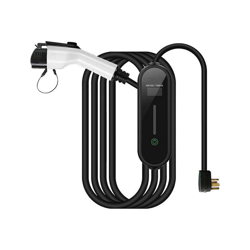
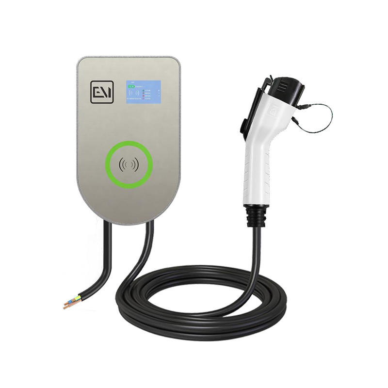
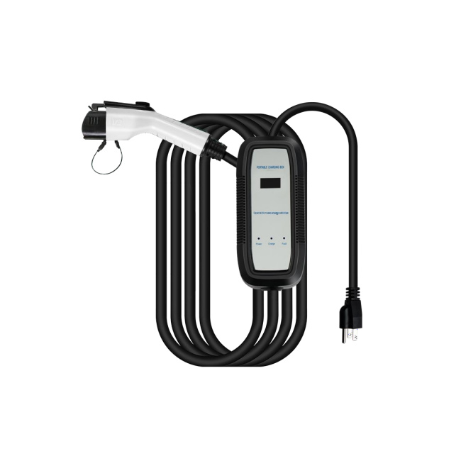
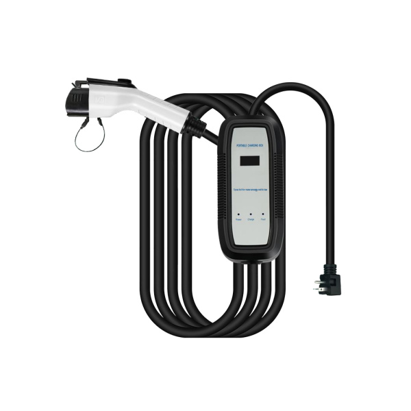 AC TYPE1 16A 3.3KW Display Screen Portable Ev Charger
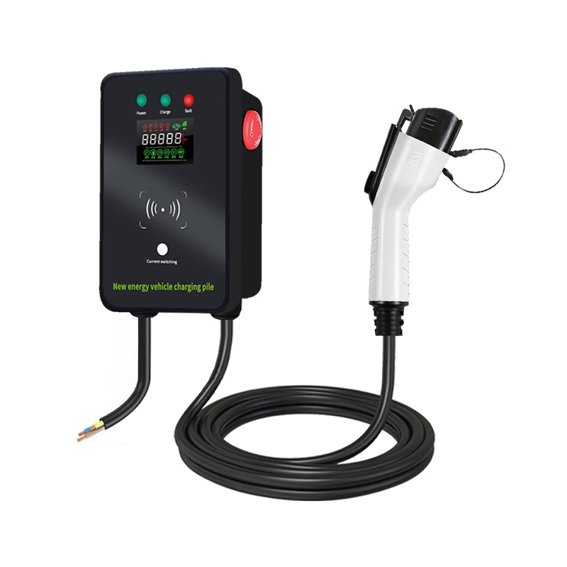
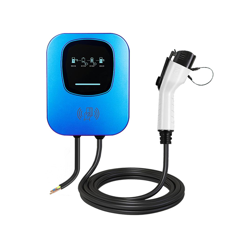
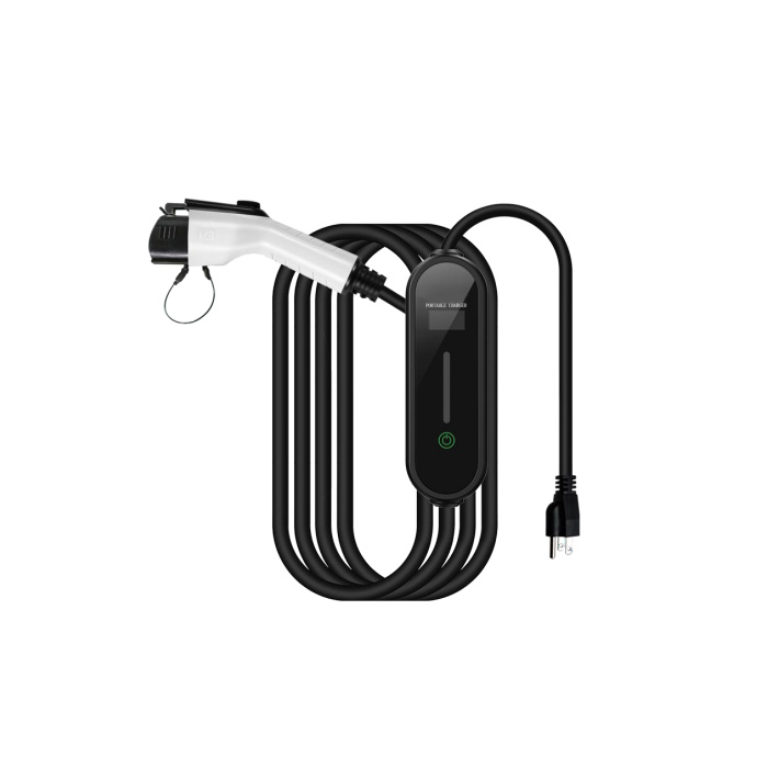
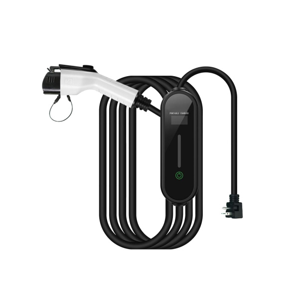 AC TYPE1 16A 3.3KW Adjustment Reservation Ev Charger
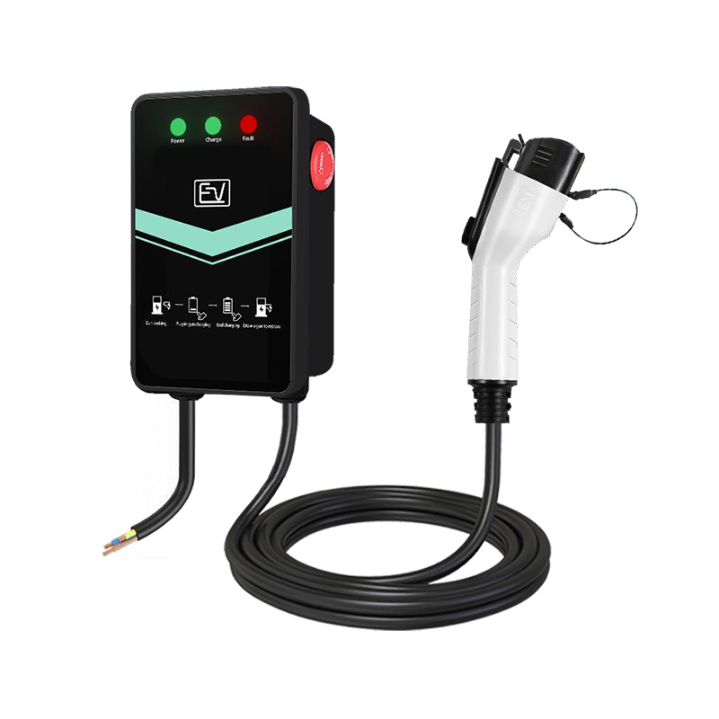
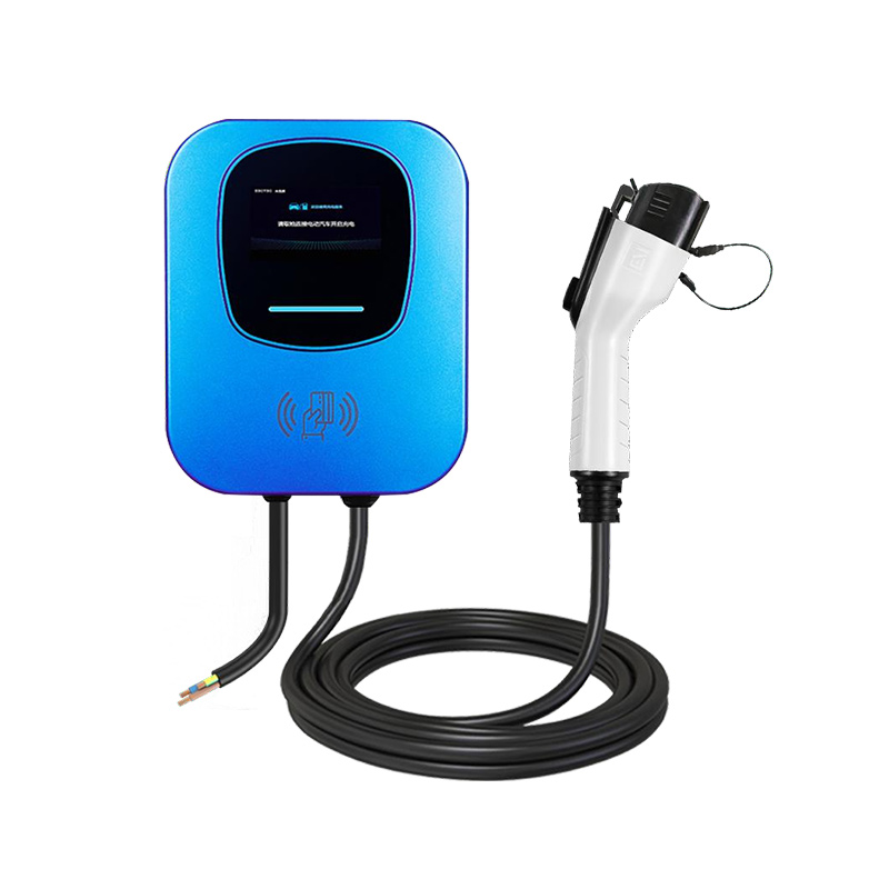
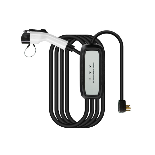
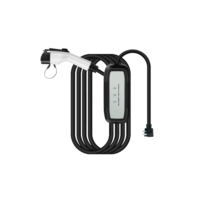 AC TYPE1 16A 3.3KW Indicator Light Portable Ev Charger
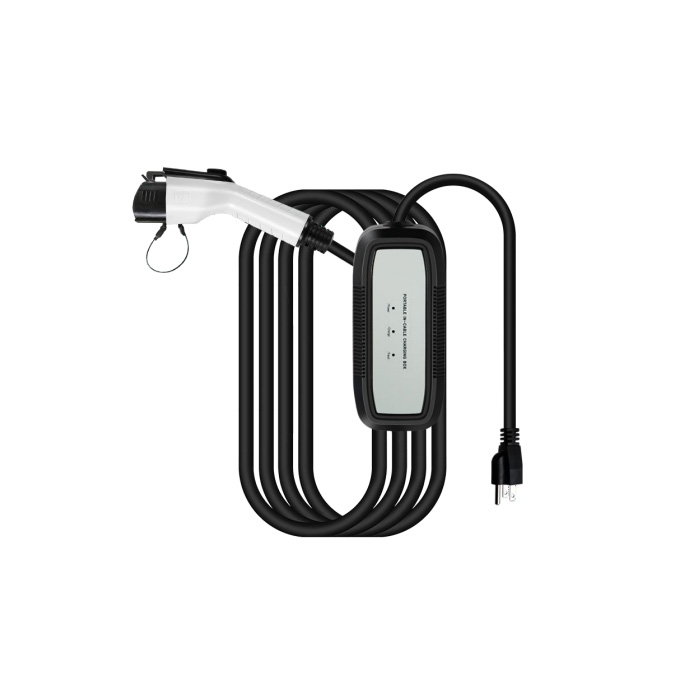 AC TYPE1 16A 3.3KW Indicator Light Portable Ev Charger
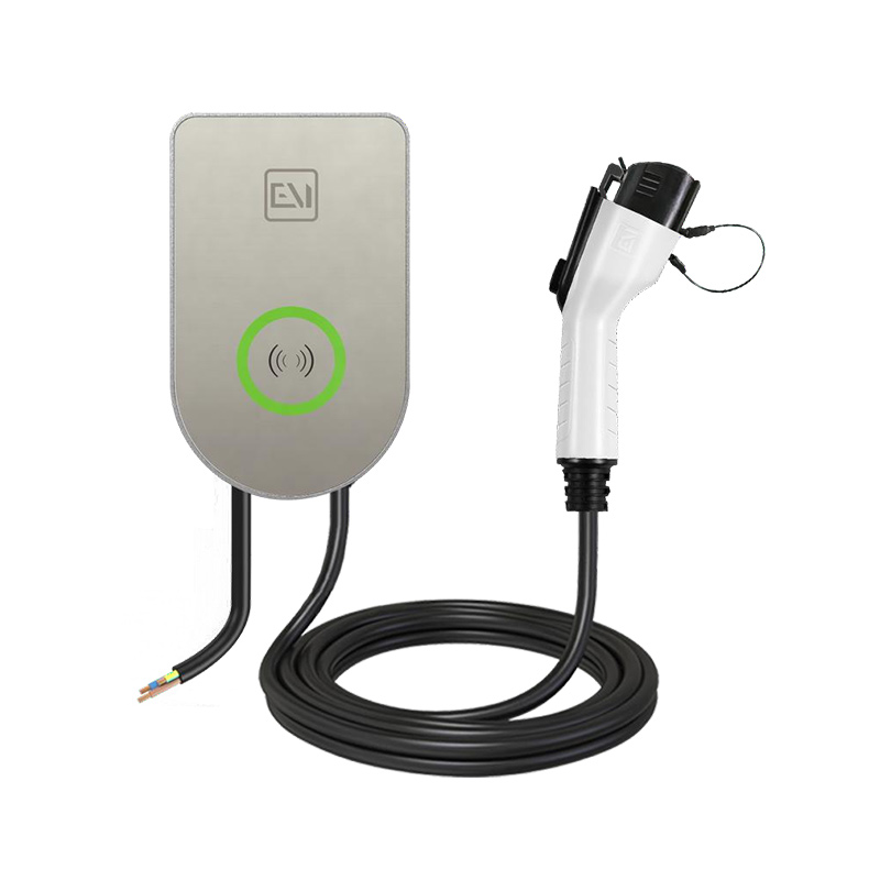
 AC TYPE1 16A 3.3KW Display Screen Portable Ev Charger
 AC TYPE1 16A 3.3KW Adjustment Reservation Ev Charger
 AC TYPE1 32A 7KW Indicator Light Portable Ev Charger
 AC TYPE1 32A 7KW Display Screen Portable Ev Charger